• Fri frakt över 249 kr
  • •
  • Snabba leveranser
  • •
  • Billiga böcker
Kundservice

Du är på sajten för privatpersoner.

Företag, bibliotek eller offentlig verksamhet?

Du handlar på classic.bokus.com, där alla dina funktioner finns intakta.
Till classic.bokus.com
Bokus logotyp. Gå till startsidan.
  • Erbjudanden
  • Nyheter
  • Student
  • Topplistor
  • Barn & ungdom
  • Bokus Play
  • E-böcker
  • Pocketböcker
  • Spel & pussel

10% rabatt på allt med kod: NYSTART10 →

Sidfot

Mina sidor

    Hjälp

    • Kundservice
    • Vanliga frågor och svar
    • Frakt och leverans
    • Retur vid ångerrätt
    • Reklamera vara
    • Betalning
    • Köpvillkor
    • Allmänna villkor
    • Information om webbplatsens tillgänglighet

    Om Bokus

    • Om oss
    • Pressrum
    • För studenter
    • För företag
    • För bibliotek och offentlig verksamhet
    • För leverantörer
    • Hållbarhet

    Populärt

    • Aktuella erbjudanden
    • Presentkort
    • Studentlitteratur
    • Nya böcker
    • Topplistor
    • Signerade böcker
    • Engelska böcker

    Inspiration

    • Boktips
    • BookTok
    • Populära bokserier
    • Barnbokskaraktärer
    • Populära författare
    Logotyp för Bokus
    Följ oss på Facebook (extern länk)Följ oss på Instagram (extern länk)Följ oss på YouTube (extern länk)Följ oss på TikTok (extern länk)
    bokus @ CookiesAnpassa cookiesIntegritetspolicyKöpvillkor
    Till Citymail hemsida (extern länk)Till Budbee hemsida (extern länk)Till Postnord hemsida (extern länk)Till Schenker hemsida (extern länk)Till Early Bird hemsida (extern länk)Till Walleys hemsida (extern länk)
    1. Naturvetenskap och teknik
    2. Teknik och industri
    3. Elektronik och kommunikationer

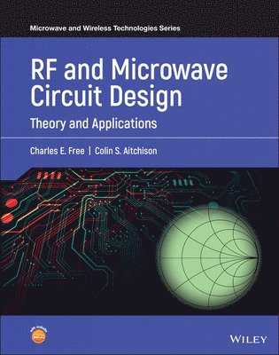
    RF and Microwave Circuit Design

    Theory and Applications

    AvCharles E. Free,Colin S. Aitchison

    Inbunden, Engelska, 2021

    Del i serien Microwave and Wireless Technologies Series

    1 136 kr

    Beställningsvara. Skickas inom 5-8 vardagar. Fri frakt över 249 kr.

    Beskrivning

    RF and Microwave Circuit Design Provides up-to-date coverage of the fundamentals of high-frequency microwave technology, written by two leading voices in the field RF and Microwave Circuit Design: Theory and Applications is an authoritative, highly practical introduction to basic RF and microwave circuits. With an emphasis on real-world examples, the text explains how distributed circuits using microstrip and other planar transmission lines can be designed and fabricated for use in modern high-frequency passive and active circuits and sub-systems. The authors provide clear and accurate guidance on each essential aspect of circuit design, from the theory of transmission lines to the passive and active circuits that form the basis of modern high-frequency circuits and sub-systems. Assuming a basic grasp of electronic concepts, the book is organized around first principles and includes an extensive set of worked examples to guide student readers with no prior grounding in the subject of high-frequency microwave technology. Throughout the text, detailed coverage of practical design using distributed circuits demonstrates the influence of modern fabrication processes. Filling a significant gap in literature by addressing RF and microwave circuit design with a central theme of planar distributed circuits, this textbook: Provides comprehensive discussion of the foundational concepts of RF and microwave transmission lines introduced through an exploration of wave propagation along a typical transmission lineDescribes fabrication processes for RF and microwave circuits, including etched, thick-film, and thin-film RF circuitsCovers the Smith Chart and its application in circuit design, S-parameters, Mason???s non-touching loop rule, transducer power gain, and stabilityDiscusses the influence of noise in high-frequency circuits and low-noise amplifier designFeatures an introduction to the design of high-frequency planar antennas Contains supporting chapters on fabrication, circuit parameters, and measurementsIncludes access to a companion website with PowerPoint slides for instructors, as well as supplementary resourcesPerfect for senior undergraduate students and first-year graduate students in electrical engineering courses, RF and Microwave Circuit Design: Theory and Applications will also earn a place in the libraries of RF and microwave professionals looking for a useful reference to refresh their understanding of fundamental concepts in the field.

    Produktinformation

    • Utgivningsdatum:2021-10-07
    • Mått:170 x 244 x 34 mm
    • Vikt:1 503 g
    • Format:Inbunden
    • Språk:Engelska
    • Serie:Microwave and Wireless Technologies Series
    • Antal sidor:528
    • Förlag:John Wiley & Sons Inc
    • ISBN:9781119114635

    Utforska kategorier

    • Elektronik och kommunikationer inom Naturvetenskap och teknik

    Mer om författaren

    Dr. Charles E. Free was formerly a Reader in Microwave Technology at the University of Surrey, United Kingdom. He specializes in RF electronics and microwave engineering and has contributed to approximately 150 scholarly publications.Professor Colin S. Aitchison was previously Chair of the European Microwave Conference and has contributed to approximately 185 scholarly publications. He was formerly Dean of the Technology faculty at Brunel University, United Kingdom.

    Innehållsförteckning

    • Preface1. RF Transmission lines1.0 Introduction1.1 Voltage, current and impedance relationships on a transmission line1.2 Propagation constant1.2.1 Dispersion1.2.2 Amplitude distortion1.3 Lossless transmission lines1.4 Matched and mismatched transmission lines1.5 Waves on a transmission line1.6 The Smith chart1.6.1 Derivation of the chart1.6.2 Properties of the chart1.7 Stubs1.8 Distributed matching circuits1.9 Manipulation of lumped impedance using the Smith chart1.10 Lumped impedance matching1.10.1 Matching a complex load impedance to a real source impedance1.10.2 Matching a complex load impedance to a complex source impedance1.11 Equivalent lumped circuit of a lossless transmission line1.12 Supplementary problems1.13 AppendicesAppendix A1.1 Coaxial cableA1.1.1  Electromagnetic field patterns in coaxial cableA1.1.2  Essential properties of coaxial cablesAppendix A1.2 Coplanar waveguideA1.2.1 Structure of coplanar waveguide (CPW)A1.2.2  Electromagnetic field distribution on a CPW lineA1.2.3 Essential properties of coplanar (CPW) linesA1.2.4  Summary of key points relating to CPW linesAppendix A1.3 Metal waveguideA1.3.1  Waveguide principlesA1.3.2 Waveguide propagationA1.3.3 Rectangular waveguide modesA1.3.4  The waveguide equationA1.3.5 Phase and group velocitiesA1.3.6  Field theory analysis of rectangular waveguidesA1.3.7 Waveguide impedanceA1.3.8  Higher-order rectangular waveguide modesA1.3.9  Waveguide attenuationA1.3.10  Sizes of rectangular waveguide, and waveguide designationA1.3.11 Circular waveguideAppendix A1.4 MicrostripAppendix A1.5 Equivalent lumped circuit representation of a transmission lineReferences2. Planar Circuit Design I: Designing using Microstrip2.0 Introduction2.1 Electromagnetic field distribution across a microstrip line2.2 Effective relative permittivity,  2.3 Microstrip design graphs and CAD software2.4 Operating frequency limitations2.5 Skin depth2.6 Examples of microstrip components2.6.1 Branch-line coupler2.6.2 Quarter-wave transformer2.6.3 Wilkinson power divider2.7 Microstrip coupled-line structures2.7.1  Analysis of microstrip coupled lines2.7.2 Microstrip directional couplers2.7.2.1 Design of microstrip directional couplers2.7.2.2 Directivity of microstrip directional couplers2.7.2.3 Improvements to microstrip directional couplers2.7.3 Examples of other common microstrip coupled-line structures2.7.3.1 Microstrip DC break2.7.3.2 Edge-coupled microstrip band-pass filter2.7.3.3 Lange coupler2.8 Summary2.9 Supplementary problems2.10 Appendix A2.1: Microstrip design graphsReferences3. Fabrication processes for RF and microwave circuits3.1 Introduction3.2 Review of essential materials parameters3.2.1 Dielectrics3.2.2 Conductors3.3 Requirements for RF circuit materials3.4 Fabrication of planar high-frequency circuits3.4.1 Etched circuits3.4.2 Thick-film circuits (direct screen printed)3.4.3 Thick-film circuits (using photoimageable materials)3.4.4 LTCC (low temperature co-fired ceramic) circuits3.4.5 Use of ink jet technology3.5 Characterization of materials for RF and microwave circuits3.5.1 Measurement of dielectric loss and dielectric constant3.5.1.1 Cavity resonators3.5.1.2 Dielectric characterization by cavity perturbation3.5.1.3 Use of  the split post dielectric resonator (SPDR)3.5.1.4 Open-resonator3.5.1.5 Free-space transmission measurements3.5.2 Measurement of planar line properties 3.5.2.1 The microstrip resonant ring3.5.2.2 Non-resonant lines3.5.3 Physical properties of microstrip lines3.6 Supplementary problemsreferences4. Planar Circuit Design II:  Refinements to basic designs4.1 Introduction4.2  Discontinuities in microstrip4.2.1 Open-end effect4.2.2 Step width4.2.3 Corners4.2.4 Gaps4.2.5 T-junctions4.3 Microstrip enclosures4.4  Packaged lumped-element passive components4.4.1 Typical packages for RF passive components4.4.2 Lumped-element resistors4.4.3 Lumped-element capacitors4.4.4 Lumped-element inductors4.5  Miniature planar components4.5.1 Spiral inductors4.5.2 Loop inductors4.5.3 Interdigitated capacitors4.5.4 MIM (metal-insulator-metal) capacitors4.6 Appendix 4.1: Insertion loss due to a microstrip gapReferences5. S-parameters5.1 Introduction5.2 S-parameter definitions5.3 Signal flow graphs5.4 Mason’s non-touching loop rule5.5 Reflection coefficient of a 2-port network5.6 Power gains of two-port networks5.7 Stability5.8 Supplementary Problems  5.9 Appendix A5.1  Relationships between network parameters    A5.1.1 Transmission parameters (ABCD parameters)A5.1.2 Admittance parameters (Y-parameters)A5.1.3 Impedance parameters (Z-parameters)References6. Microwave Ferrites6.1 Introduction6.2 Basic properties of ferrite materials6.2.1 Ferrite materials6.2.2 Precession in ferrite materials6.2.3 Permeability tensor6.2.4 Faraday rotation6.3 Ferrites in metallic waveguide6.3.1 Resonance isolator6.3.2 Field displacement isolator6.3.3 Waveguide circulator6.4 Ferrites in planar circuits6.4.1 Planar circulators6.4.2 Edge-guided-mode propagation6.4.3 Edge-guided-mode isolator6.4.4 Phase shifters6.5 Self-biased ferrites6.6 Supplementary problemsReferences7. Measurements7.1 Introduction7.2 RF and Microwave connectors7.2.1 Maintenance of connectors7.2.2 Connecting to planar circuits   7.3 Microwave vector network analyzers7.3.1 Description and configuration7.3.2 Error models representing a VNA7.3.3 Calibration of a VNA7.4 On-wafer measurements7.5 Summary  References8. RF Filters8.1 Introduction8.2 Review of filter responses8.3 Filter parameters8.4 Design strategy for RF and microwave filters8.5 Multi-element low-pass filter8.6 Practical filter responses8.7 Butterworth (or maximally-flat) response8.7.1 Butterworth low-pass filter8.7.3 Butterworth band-pass filter8.7.3 Butterworth band-pass filter8.8 Chebyshev (equal ripple) response8.9 Microstrip low-pass filter, using stepped impedances8.10 Microstrip low-pass filter, using stubs8.11     Microstrip edge-coupled band-pass filters  8.12      Microstrip end-coupled band-pass filters8.13      Practical points associated with filter design8.14      Summary8.15   Supplementary problems8.16 Appendix A8.1 Equivalent lumped T-network representation of a transmission lineReferences9. Microwave Small-Signal Amplifiers9.1 Introduction9.2 Conditions for matching9.3 Distributed (microstrip) matching networks9.4 DC biasing circuits9.5 Microwave transistor packages9.6 Typical hybrid amplifier9.7 DC finger breaks9.8 Constant gain circles9.9 Stability circles9.10  Noise circles9.11 Low-noise amplifier design9.12  Simultaneous conjugate match9.13 Broadband matching9.14 Summary9.15 Supplementary problemsReferences10. Switches and Phase Shifters10.1 Introduction10.2 Switches10.2.1 PIN diodes10.2.2 FETs (Field Effect Transistors)10.2.3 MEMS (Microelectromechanical Systems)10.2.4 IPCS (Inline Phase Change Switch) devices10.3 Digital phase shifters10.3.1 Switched-path phase shifter10.3.2 Loaded-line phase shifter10.3.3 Reflection-type phase shifter10.3.4 Schiffman 90 phase shifter10.3.5 Single switch phase shifter10.4 Supplementary problemsReferences11. Oscillators11.1 Introduction11.2 Criteria for oscillation in a feedback circuit11.3 RF (transistor) oscillators11.3.1 Colpitts oscillator11.3.2 Hartley Oscillator11.3.3 Clapp-Gouriet Oscillator  11.4 Voltage controlled oscillator (VCO)11.5 Crystal-controlled oscillators11.5.1 Crystals11.5.2 Crystal-controlled oscillators11.6 Frequency synthesizers11.6.1 The phase-locked loop11.6.1.1 Principle of a phase-locked loop11.6.1.2 Main components of a phase-locked loop11.6.1.3 Gain of a phase-locked loop11.6.1.4 Transient analysis of a phase-locked loop11.6.2 Indirect frequency synthesizer circuits 11.7 Microwave oscillators11.7.1 Dielectric resonator oscillator11.7.2 Delay line stabilized oscillator11.7.3 Diode oscillators11.7.3.1 Gunn diode oscillator11.7.3.2 IMPATT diode oscillator11.8 Oscillator noise11.9 Measurement of oscillator noise11.10 Supplementary problemsReferences12. RF and Microwave Antennas12.1 Introduction12.2 Antenna parameters12.3 Spherical polar coordinates12.4 Radiation from a Hertzian dipole12.4.1 Basic principles12.4.2 Gain of a Hertzian dipole12.5 Radiation from a half-wave dipole12.5.1 Basic principles12.5.2 Gain of a half-wave dipole12.5.3 Summary of the properties of a half-wave dipole12.6 Antenna arrays12.7 Mutual impedance12.8 Arrays containing parasitic elements12.9 Yagi-Uda array12.10 Log-periodic array12.11 Loop antenna12.12 Planar antennas12.12.1 Linearly polarized patch antennas12.12.2 Circularly polarized planar antennas 12.13  Horn antennas12.14 Parabolic reflector antennas12.15 Slot radiators12.16 Supplementary problems12.17 Appendix:  Microstrip design graphs for substrates with r = 2.3References13. Power Amplifiers and Distributed Amplifiers13.1 Introduction13.2 Power amplifiers13.2.1 Overview of power amplifier parameters13.2.1.1  Power gain13.2.1.2  Power added efficiency (PAE)13.2.1.3 Input and output impedances13.2.2 Distortion13.2.2.1 Gain compression13.2.2.2 Third-order intercept point13.2.3 Linearization13.2.3.1 Pre-distortion13.2.3.2 Negative feedback13.2.3.3 Feedforward  13.2.4 Power combining13.2.5 Doherty amplifier13.3 Load matching of power amplifiers13.4 Distributed amplifiers13.4.1 Description and principle of operation13.4.2 Analysis13.5 Developments in materials and packaging for power amplifiersReferences14. Receivers and Sub-Systems14.1 Introduction14.2 Receiver noise sources14.2.1 Thermal noise14.2.2 Semiconductor noise14.3 Noise measures14.3.1 Noise figure (F)14.3.2 Noise temperature (Te)14.4 Noise figure of cascaded networks14.5 Antenna noise temperature14.6 System noise temperature14.7 Noise figure of a matched attenuator14.8 Superhet receiver14.8.1 Single-conversion superhet receiver14.8.2 Image frequency14.8.3 Key figures-of-merit for a superhet receiver14.8.4 Double-conversion superhet receiver14.8.5  Noise budget graph for a superhet receiver14.9 Mixers14.9.1 Basic mixer principles14.9.2 Mixer parameters14.9.3 Active and passive mixers14.9.4 Single-ended diode mixer14.9.5 Single balanced mixer14.9.6 Double balanced mixer14.9.7 Active FET mixers14.10 Supplementary problems14.11 AppendicesAppendix A14.1 Error function tableAppendix A14.2 Measurement of noise figureReferencesAnswers to selected supplementary problems